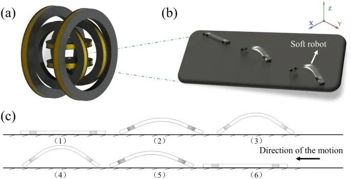
Fig. W1 a Schematic diagram of the magnetically driven soft robot. b Schematic diagram of the soft robot’s motion. c Steps in the soft robot’s motion cycle

Fig. W2 a Deformation of the soft robot. b Force analysis of the soft robot. c The relationship between the strength of the magnetic field and the current

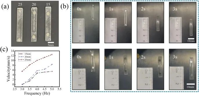
Fig. W3 a Soft robots with different magnet spacings: 25 mm, 20 mm, and 15 mm, from left to right. b Images of soft robots with magnetic spacings of 25 mm and 15 mm driven by the same magnetic field. c Movement speed of strip-shaped soft robots with different magnet spacings (25 mm, 20 mm, and 15 mm)

Fig. W4 Climbing testing at different slopes. a Movement at a slope of 0°. b Movement at a slope of 5°. c Movement at a slope of 10°. d Movement at a slope of 15°. e Climbing speeds at different slopes (0°, 5°, 10°, and 15°)
以上文章转载于微信公众号国际仿生工程学会,如有侵权,请及时联系我们修改或进行删除。
Information Publisher: Honglin Shen
Information Release Unit: School of Electromechanical and Automotive Engineering, Yantai University, Yantai
Information Source: https://mp.weixin.qq.com/s/UHchSN4UgDEYpdSvsyevQQ

